Home > SMT Assembly News
The solder has not fully filled the plated through hole in Figure 1. This is due either to the pre-heat being set too low or poor flux application. In both cases, a check on the process parameters should eliminate the problem.
This is a common problem seen when a company changes over from a foam fluxer to a spray flux unit; it is due to the poor penetration of flux into the through hole.
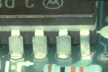
Figure 1: Solder has not fully filled the plated through hole here.
Poor or incomplete hole fill is normally a fluxing or heating issue. It is uncommon for it to be a printed board problem. In Figure 2, the poor hole fill is due to pre heat settings. The solder has wetted the leads of the device but failed to wet the surface of the through hole.
As a guide, the topside temperature of the printed board just before wave contact should be 100-110°C. This is generally true for double sided and multilayer boards. Single-sided boards will be processed at slightly lower temperatures as no solder penetration is needed.
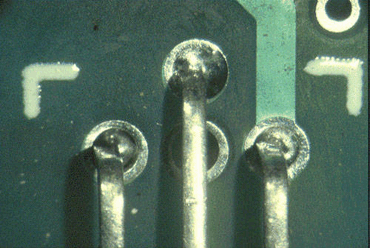
Figure 2: The solder has failed to wet the surface of the through-hole here.
The solder has not fully filled the plated through hole in Figure 3. This is either due to the pre heat operation being set too low or poor flux application. In both cases a check on the process parameters should eliminate the problem.
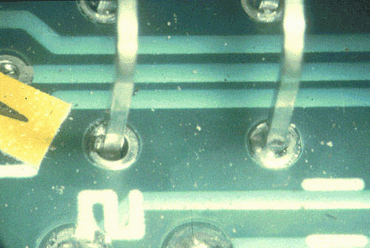
Figure 3: The solder has not fully filled the plated through hole on the left.
In Figure 4, one hole has filled and the second has not, which should indicate the problem is less likely to be a printed board problem. Close examination shows that the solder has solidified on one hole due to the thermal demand of the component. By raising the pre heat or by increasing wave contact time this problem should be simply overcome.
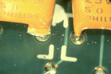
Figure 4: One hole has filled; the other has not.
Poor hole fill can be caused by incorrect pre heat, no flux or a total miss of the solder wave. In Figure 5 there is no evidence of solder in the through hoes or vias. It is more than likely that the board failed to make contact with the wave which could be due to wave height, damaged fingers or pallets not being maintained. Incorrect loading of the board in to the systems may also have caused this fault.
It is possible that the quality of the through hole plating may have been responsible, but this is less likely to be the case as it would be very apparent on other boards in the batch.
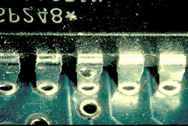
Figure 5: It is likely that this board failed to make contact with the wave.
The example of poor hole fill in Figure 6 is fairly unique as the problem is due to the legend on the printed board. Close examination shows that poor design rules have allowed the legend to contaminate the top of the plated through holes. The solder has failed to rise in the hole or wet across the surface of the pads. In this case there is no benefit from the legend and new design rules need to be applied.
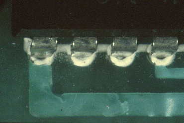
Figure 6: The legend on this PCB has contaminated the top of the plated through holes.
Figure 7 shows poor wetting of the surface of the pads and is likely to be due to the thickness of the tin/lead coating. Solder leveling often leaves a thin deposit on the surface of the pads and on the edge of the hole. This defect is often referred to as the weak knee effect, where the solder fails to wet over the knee of the hole and on to the pads. Poor hole fill can also be due to the pre-heat operation being set too low or poor flux application. In both cases a check on the process parameters should eliminate the problem.
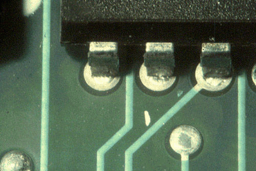
Figure 7: An example of the “weak knee” effect.
Keywords:
SMT Reflow Oven, Lead free Reflow Oven, Reflow Oven Manufacturer, LED reflow oven, PCB Reflow Oven, Nitrogen Reflow Oven, Dual Rail Reflow Oven, China Reflow Oven, wave soldering machine, Dual Rail Wave Soldering Machine, Nitrogen Wave Soldering Machine, Wave Soldering Machine Manufacturer.




Contact: Mr Tommy
Phone: +86 13691605420
Tel: +86 -755-85225569
Email: tommy@flason-smt.com
Add: 94#,Guangtian Road,Songgang Street,Bao an District Shenzhen China